
Throughout history, humans, at some point, became aware of the limits of carrying loads directly. At a certain point, they began dragging loads along the ground, then placed an intermediary between the load and the ground, both to protect the load and to reduce the effort involved — or to haul more.
The sledge was born. Later, its shapes were improved, and then the wheel was invented. The wheel, however, cannot meet every need, and the sledge remained the solution for cases where the ground’s mechanical resistance is insufficient to bear a significant contact pressure. The sledge has remained the means of transport used on soft ground such as mud and snow.
In the case of expeditions across ice caps, each organisation used its own model of light sledge; however, few models of sledges for heavy loads have ever existed. Until the start of the Concordia project, the articulated models available in 1990 were used, but these proved either too heavy or too fragile for intensive use. This led to the decision to create a more suitable family of sledges, designed in-house.
There was the exception that proves the rule. Diversifying ski-based solutions, chassis fitted with passive track axles were used. This solution was partly satisfactory, but only partly, as the assembly remained a mechanical construction and therefore subject to maintenance. Furthermore, it was not possible to find on the market an elastomer track-manufacturing compound genuinely validated for low temperatures, nor widths that would keep contact pressures within admissible limits (200-400 hPa).
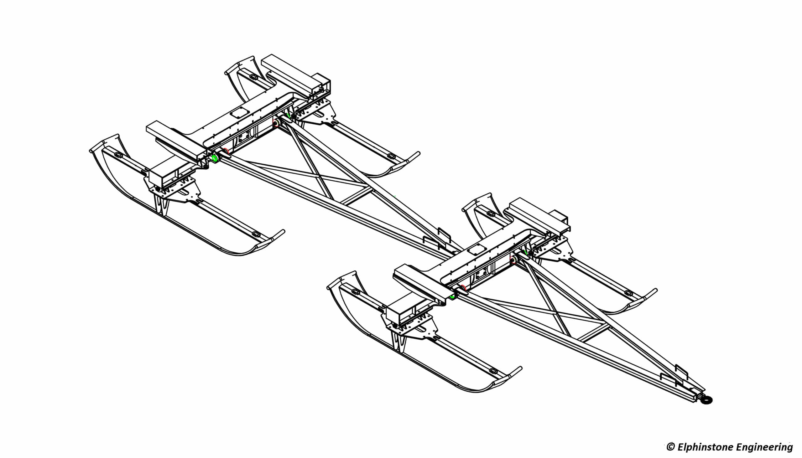
With drawbars but without deck – 12 t capacity
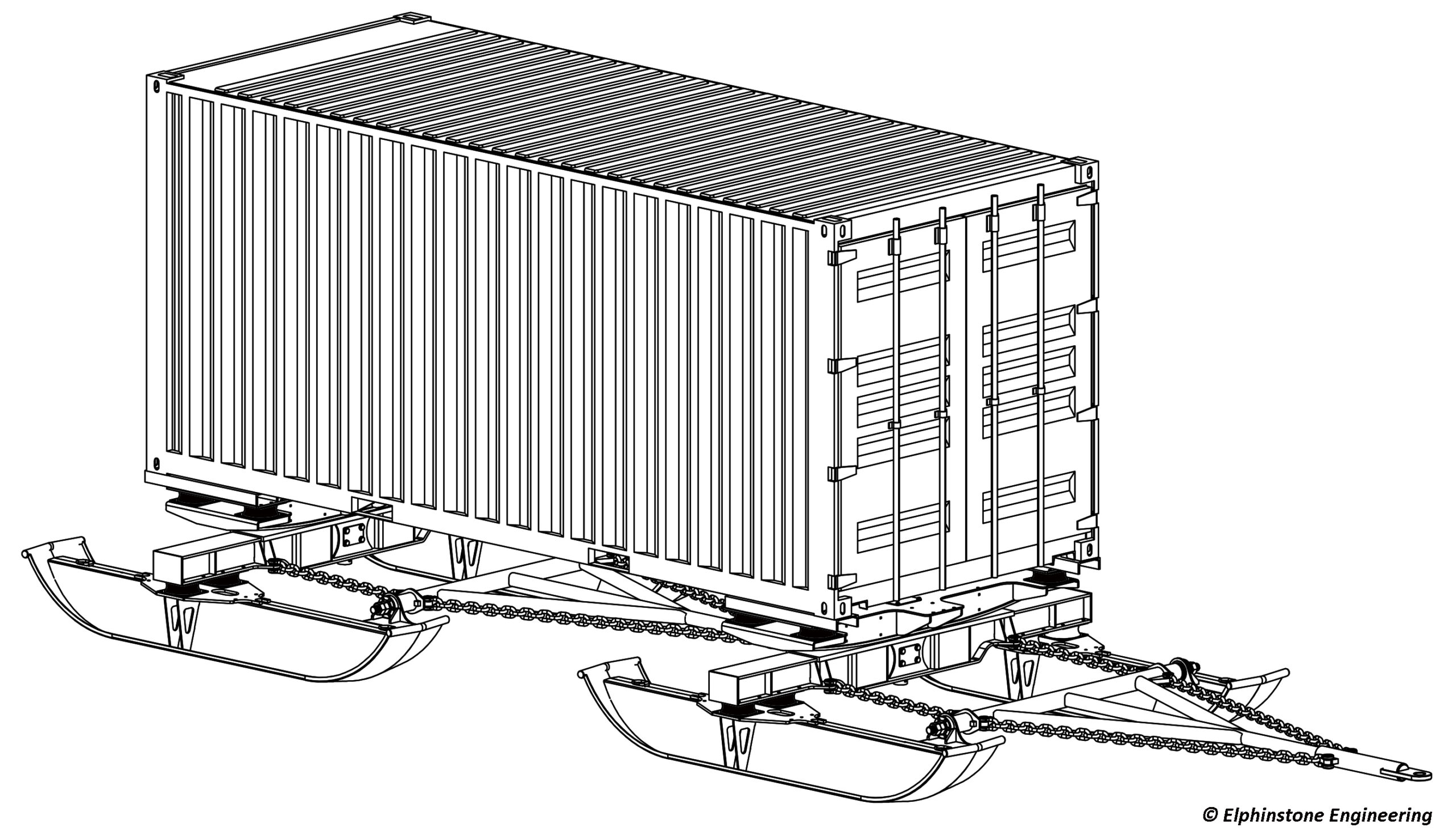
With chains, without deck – capacity 12 t
1 – Sledges on skis
A sledge is sized according to the loads it will carry — the size of the load-bearing elements and the surface area of the skis. As part of a train, it must also transmit the traction effort to the following sledge and, at its contact zone, must not damage the travel surface, which by nature offers little resistance to deformation. Several models were created to suit different circumstances and the products to be transported, on the principle of adapting the vehicle to the load, all within the overall principle of compromise:
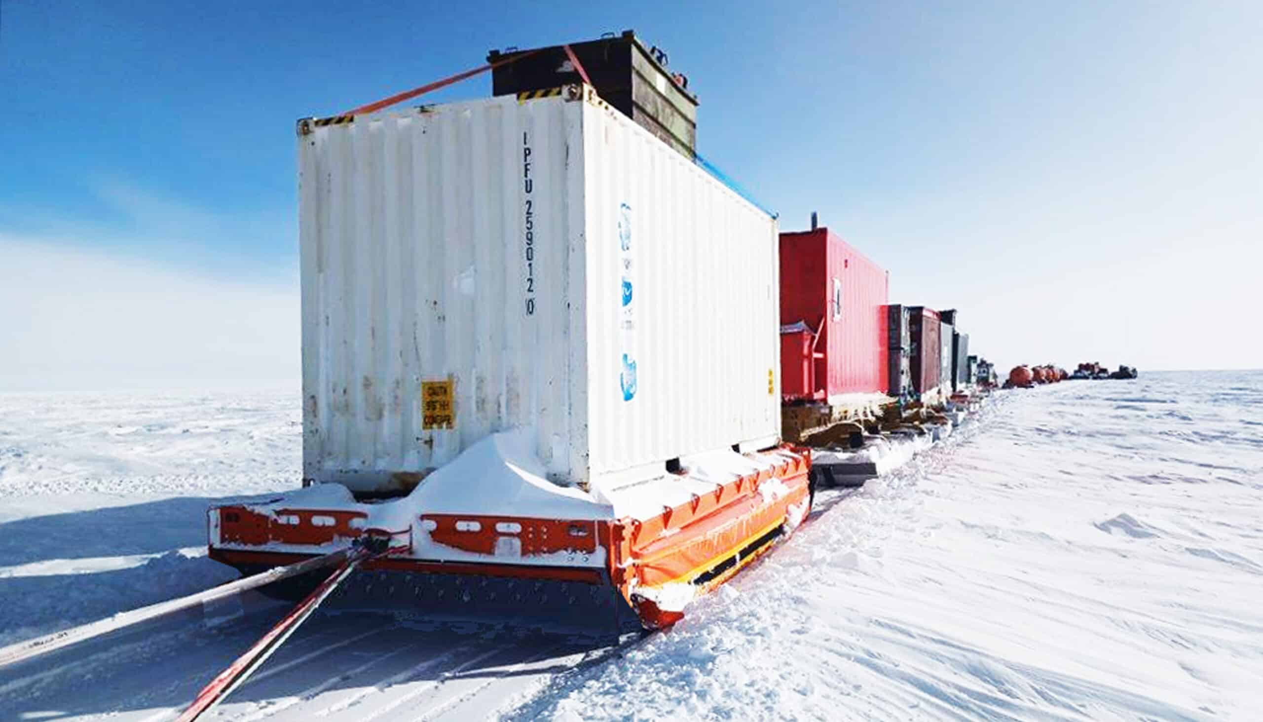
- Multi-purpose sledges for bulk loads and 20-foot containers
- Sledges specialised for 20-foot containers (without a deck – the container itself forms the body of the sledge). A modification allows use with 40-foot containers
- Multi-purpose sledges for bulk loads and 40-foot containers
- Tanker sledges (the tank itself forms the body of the sledge) of 12 m³, for the convoy’s own fuel
- Later, tanker sledges of the same design principle, of 26 m³ and 32 m³, for transporting fuel for the station.
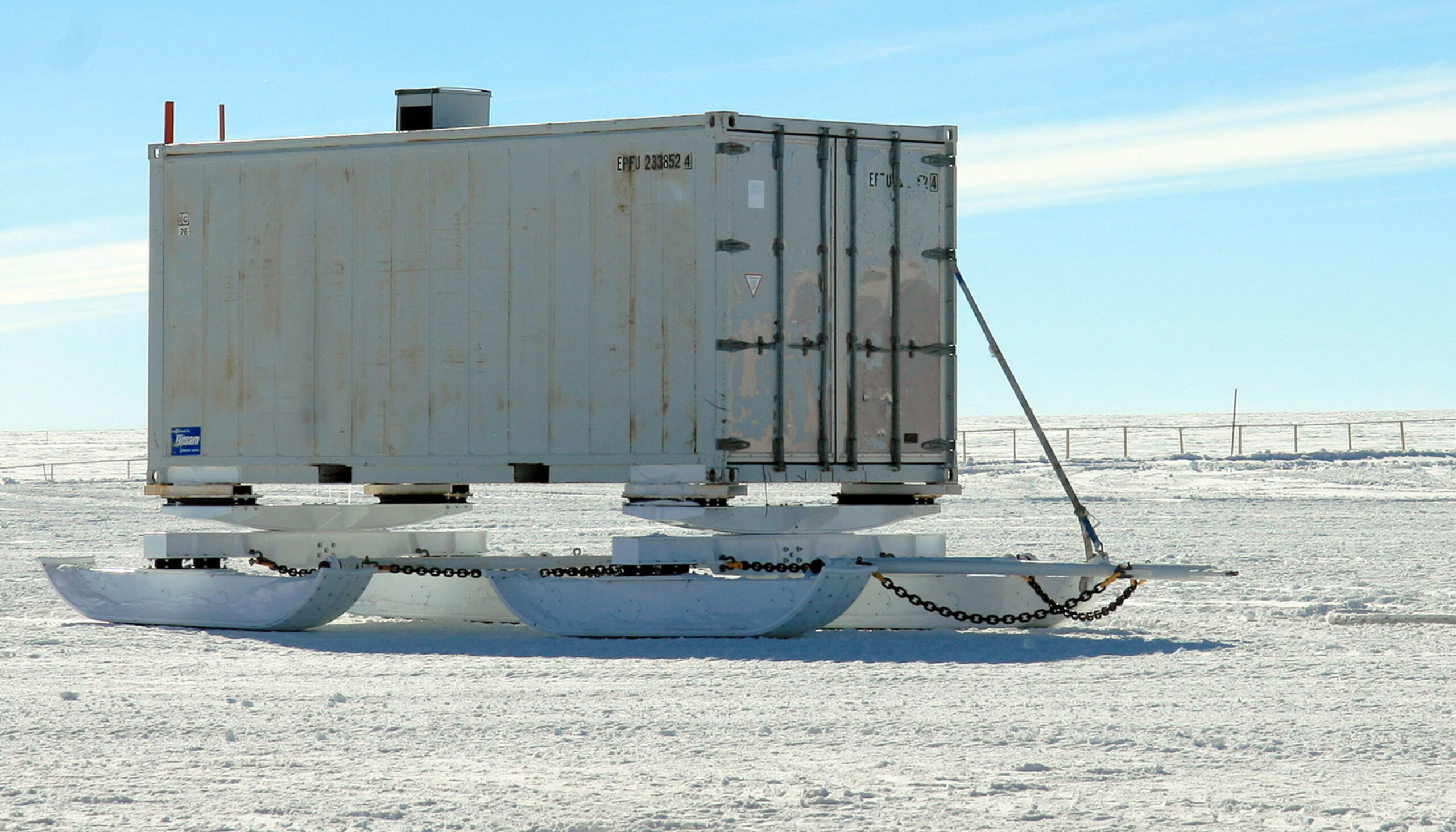
Loaded with a reefer Cntr
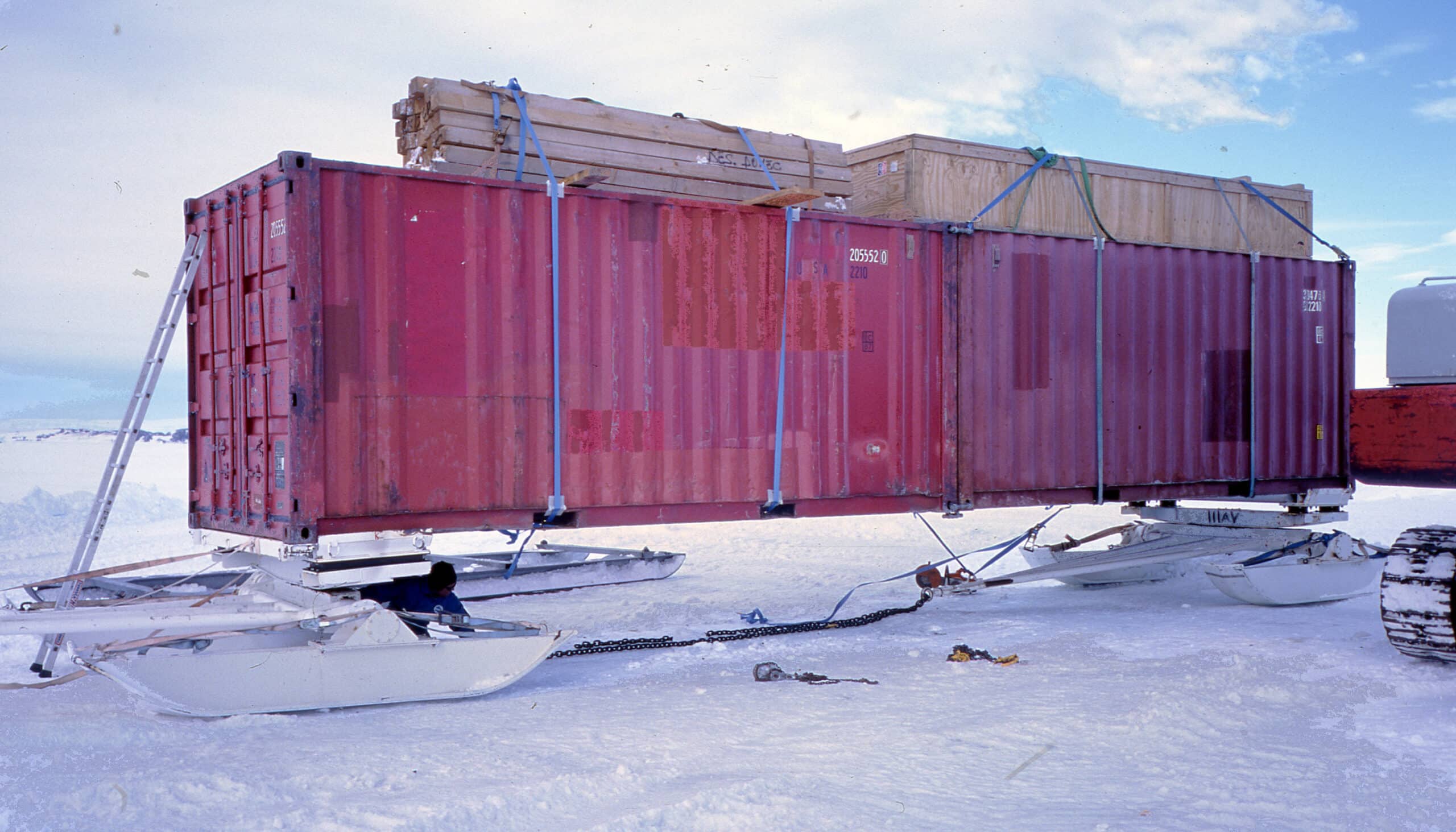
Currently extended to 40 feet
1.1 – 20-foot sledges: After a failed attempt to copy existing sledges, it was decided to move away from that approach and build a sledge without crossed chains, with a deck connected to the axles supporting the skis via deformable elastomer blocks (validated down to -50 °C) and without play, avoiding shocks on start-up. All connections are made via outer and inner drawbars, transmitting the traction forces. This first sledge was later fitted with a wider deck, extending its versatility. A second evolution saw the addition of chains for transmitting the traction effort. The chains, running over the tips of the skis, help keep the ski flat and provide a self-levelling effect while also allowing a reduction in the sledge’s height.
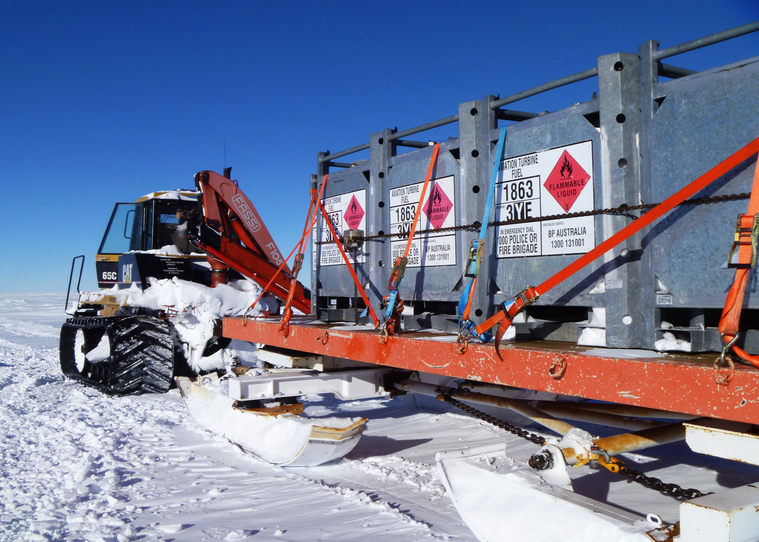
Loaded with bulk
Currently extended to 40 feet
1.2 – 40-foot sledge: The 40-foot sledge derives from the tracked chassis manufactured by Elphinstone Engineering in Tasmania, with the tracked axles replaced by skis. These sledges are fitted with multi-purpose decks and can accept bulk loads, 2 x 20-foot containers, or 1 x 40-foot container. The skis on these sledges, which can be very long — up to 6 m —, were later fitted with sway limiters to stop the rear skis from digging into the track.
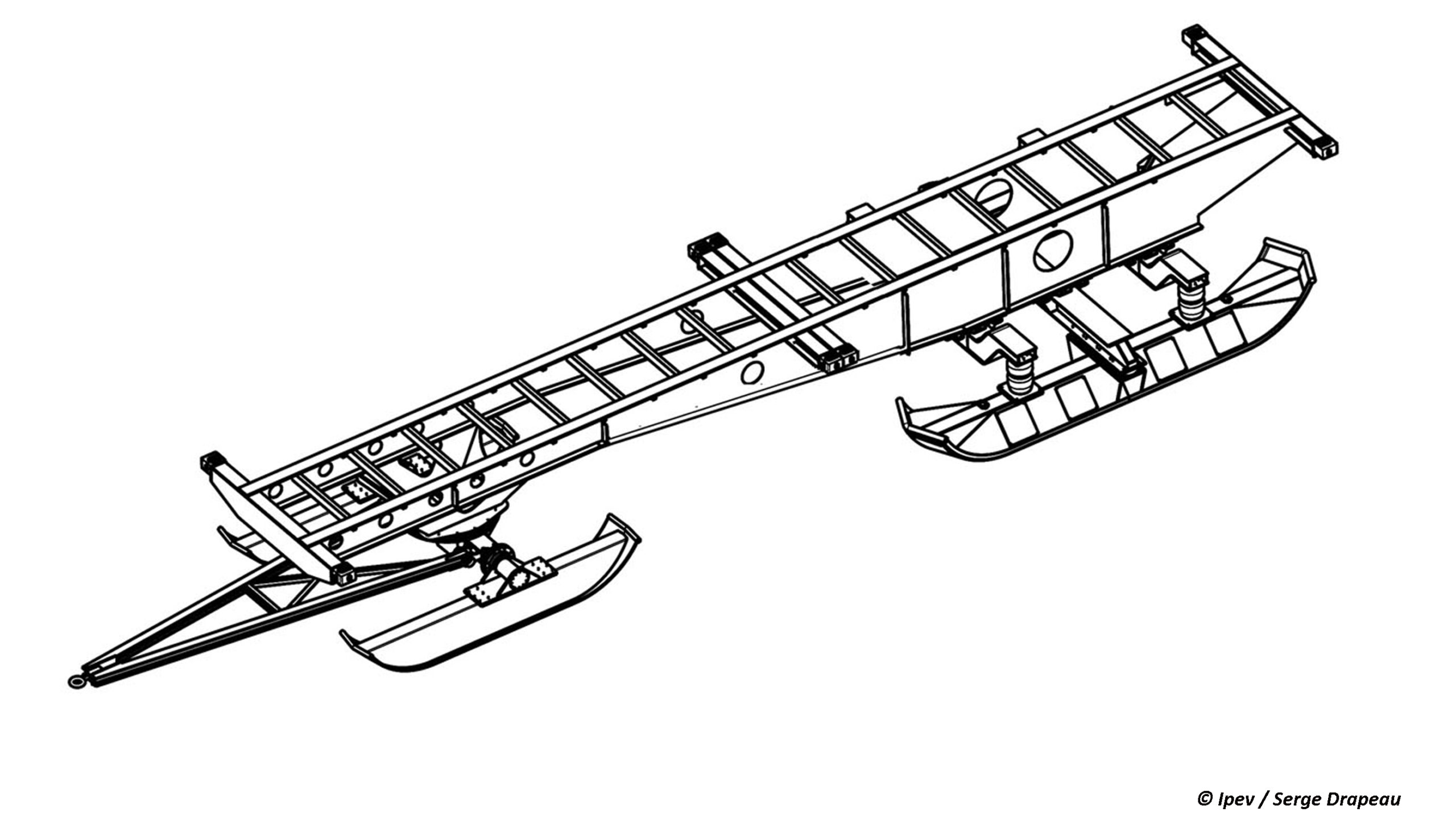
40′ cargo sled (trailer style)
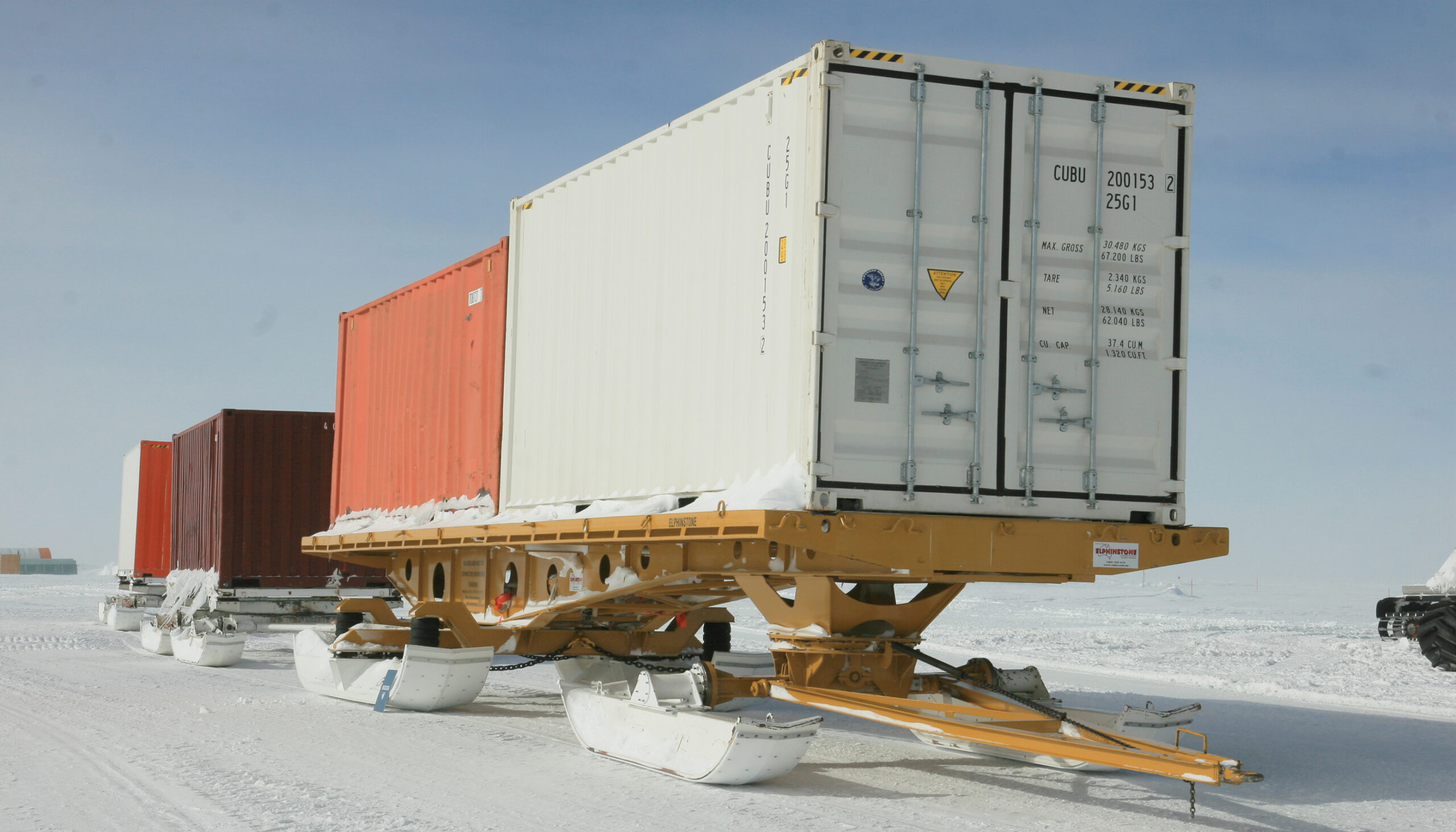
Sledge (trailer style) loaded
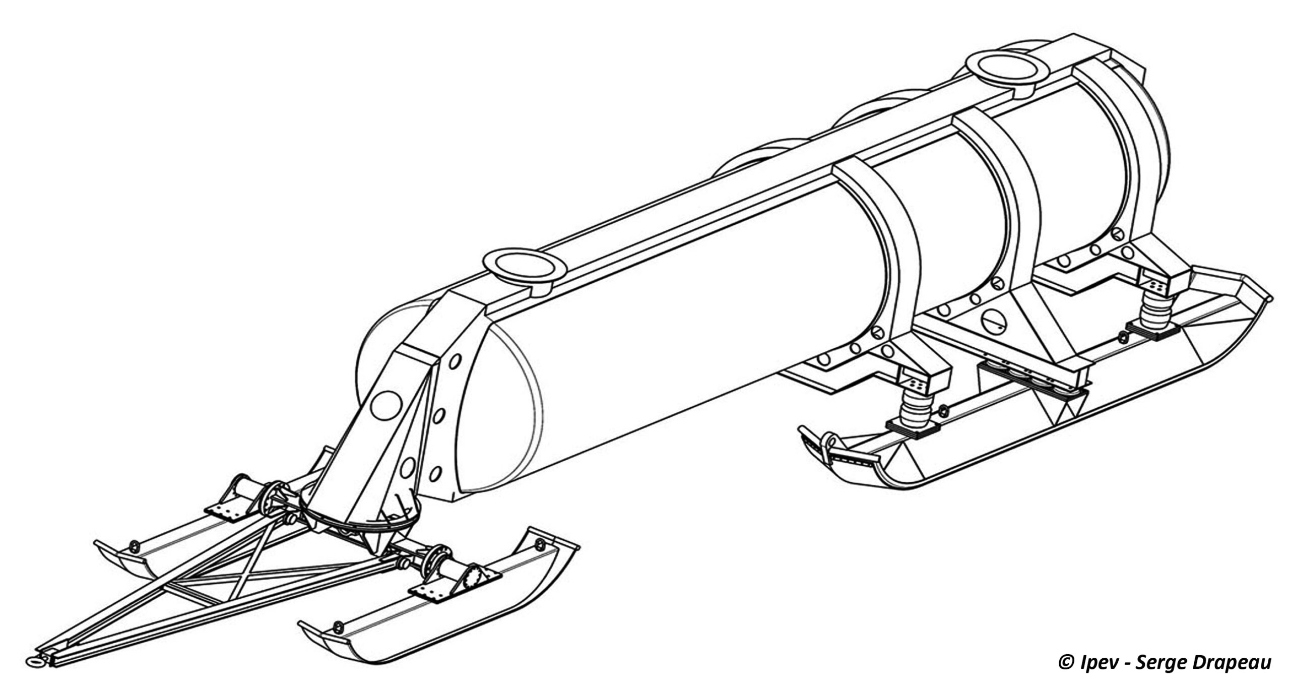
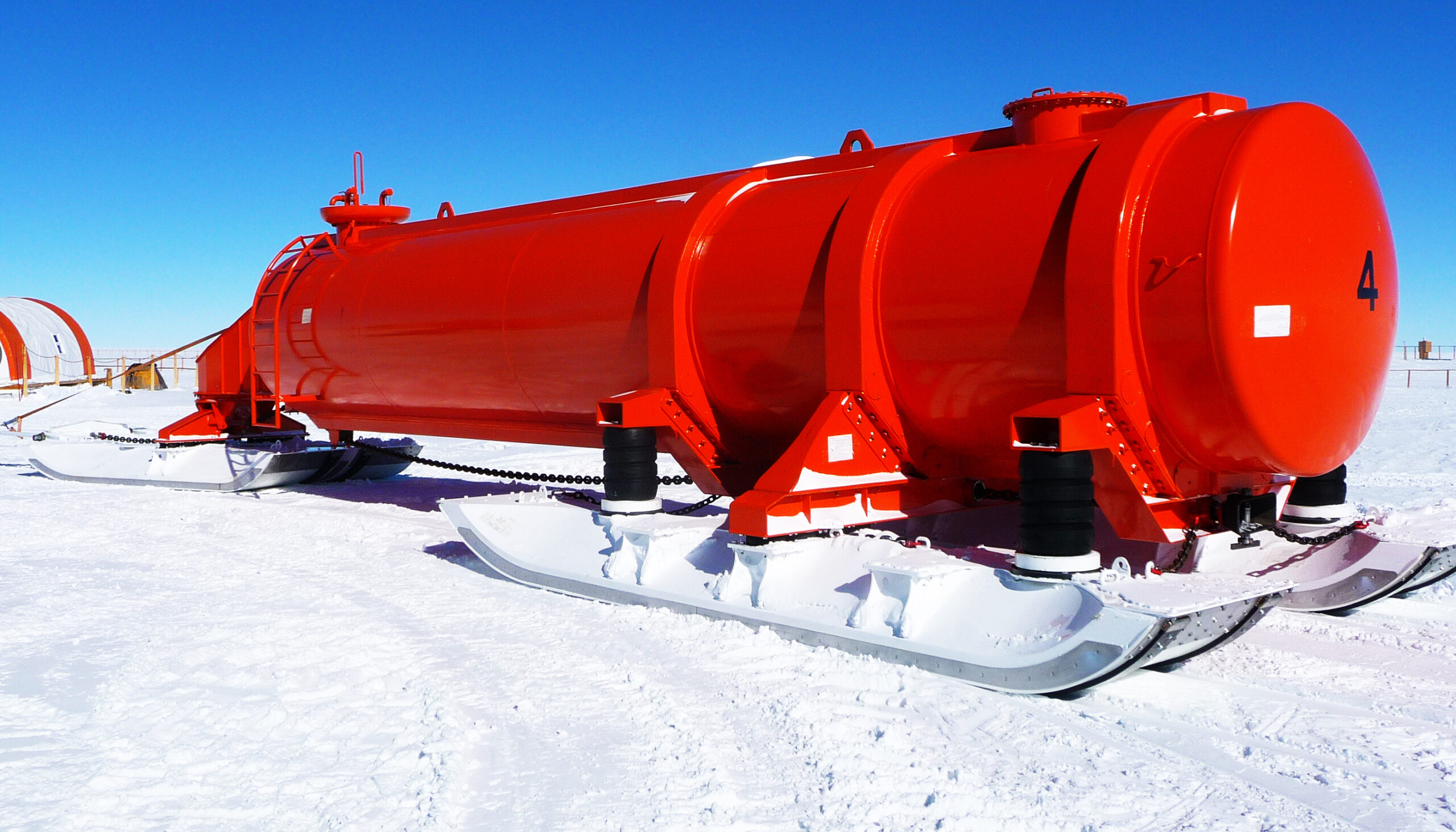
1.3 – The traverse fuel sledge, 12 m³: The principle behind this specialised sledge lies in using the tank itself as the structural element connecting the skis. The tank rests on three pairs of elastic joints (each providing a three-degree-of-freedom connection) on two skis, each made up of two articulated sections. The 12 m³ tank is built from standard components, using a tube 2 m long and 2.4 m in diameter. A flexible double liner can be fitted inside the tank. The volume of fuel carried in each tank may seem small, but it allows partly emptied tanks to be dropped off fairly quickly (roughly every day and a half) and helps maintain, as the convoy progresses towards its destination, an even balance of loads between the trains. Each tanker sledge left along the route holds part of the fuel intended for the return journey.
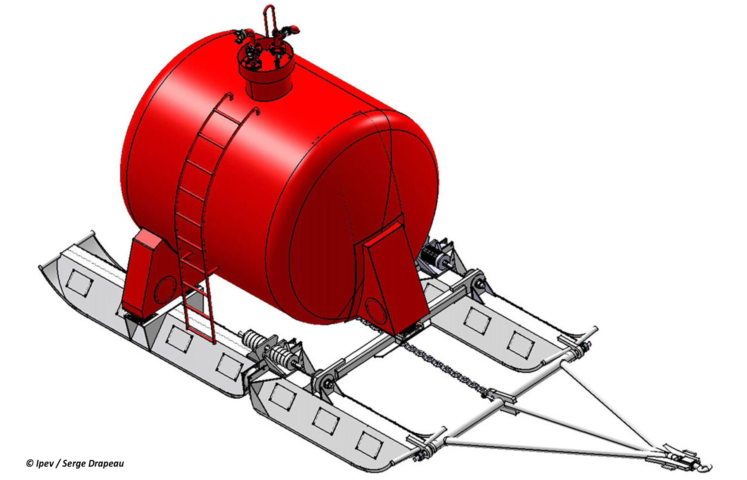
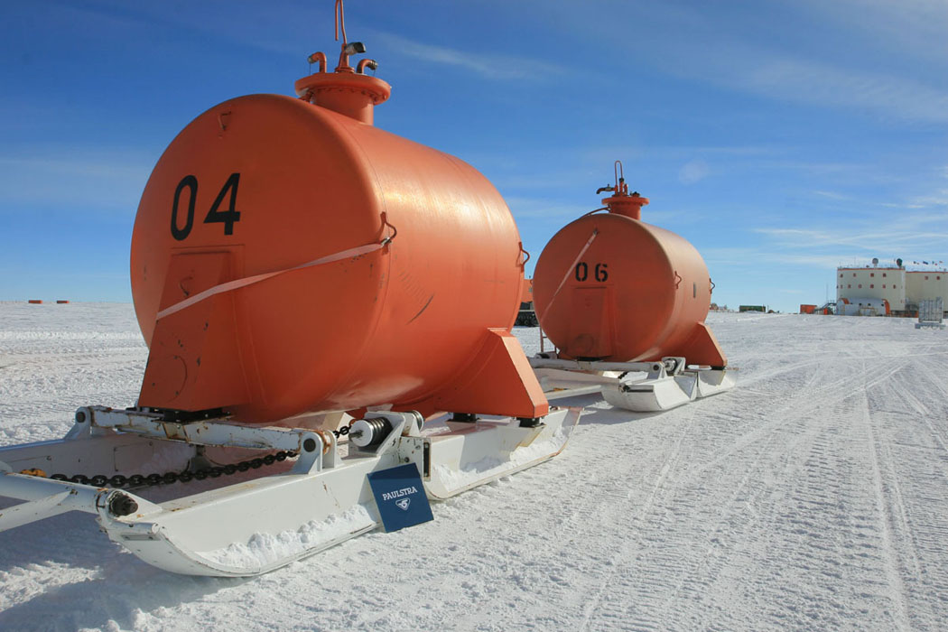
1.4 – The station tanker sledge, 26 m³ or 32 m³: Unlike the 12 m³ sledge, this one was not designed to be emptied progressively along the route. It incorporates elements from the 40-foot sledge and combines the latest self-levelling innovations. The length of the tank allows good separation between the front and rear skis, which moves the skis away from the front hitch and reduces the stresses transmitted through the suspension. The skis were designed to maintain a ground pressure of 30 kPa.
2 – Unconventional sledges
2.1 – Sheet sledge: A return to the basic definition of a sledge was initiated by USARP in early 2010. Rather than dragging the load directly over the ground, the idea was to use a large sheet of HD polyethylene placed under the load. The principle of placing a sheet under a heavy load to move it, rather than lifting it, is a well-known one. It is used for transporting fuel over particularly flat terrain such as sea ice and certain low-wind areas, but is harder to apply to bulk loads. The sheet is attractive because it has almost no dead weight of its own and produces a very low contact pressure. It does not deform the track, and traction effort is reduced compared with a conventional sledge, but there is a risk of contamination on hard, uneven terrain.
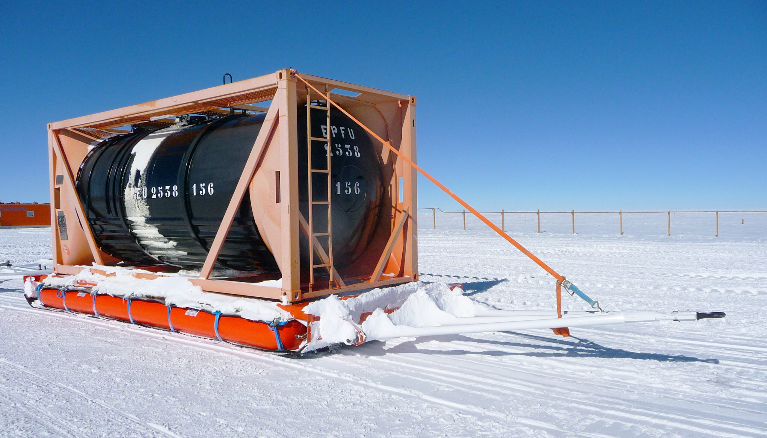
With 24m3 tank container
Foam mattress
2.2 – Air-cushion sledge: For material loads, a platform the size of a container is mounted on an air cushion 0.8 m thick. The air cushion, made up in this case of 4 envelopes 800 mm in diameter, acts as an intermediary between the load and the surface of the track. Like the sheet sledge, it rests on a large sheet of polyethylene. The cushion absorbs all ground deformations in the same way the sledges’ skis do. The difficulties lie in keeping the envelopes in place between the sheet and the deck, since the envelopes, shifting between ellipsoidal sections of varying sizes, deform according to atmospheric pressure as well as the forces transmitted by uneven ground.
2.3 – Foam-mattress sledge: This is an evolution of the air-cushion sledge. The elastic principle here is provided by compressible foam blocks, with no memory effect and retaining their flexibility down to -45 °C. The mattress is made up of 3 foam blocks of 6 m x 1 m x 0.75 m. It keeps the principle of hugging the ground without digging trenches, while offering limited traction effort. It solves the two problems of keeping the envelopes in place and the risk of air leaks. The mattress’s response under load is constant; internal air-pressure issues are eliminated. The envelopes are no longer circular in cross-section but square, which simplifies keeping them in place. The straps linking the sheet to the deck are no longer needed. What remains to be improved is the fin/keel system limiting yaw. After unsuccessful trials with blade-style fins, a system of edges placed under the sheet, without stiffening it, is currently being tested. As foam has non-negligible mass (100 kg/m³), it is preferable to reserve this sledge for heavy loads (15 to 25 t).