
Thermal insulation and heating
Heat loss, heating and insulation are interdependent facets of the constraint of minimising fuel consumption, both to reduce the quantities to be transported by convoy and to limit the local impact. The project is located at Dome C, one of the coldest places on the planet, where winter temperatures average around -65°C and sometimes drop below -80°C. With standard indoor temperatures, the thermal differential between outside and inside can thus reach 100°C.
Power station Heating cooling networks
A few figures
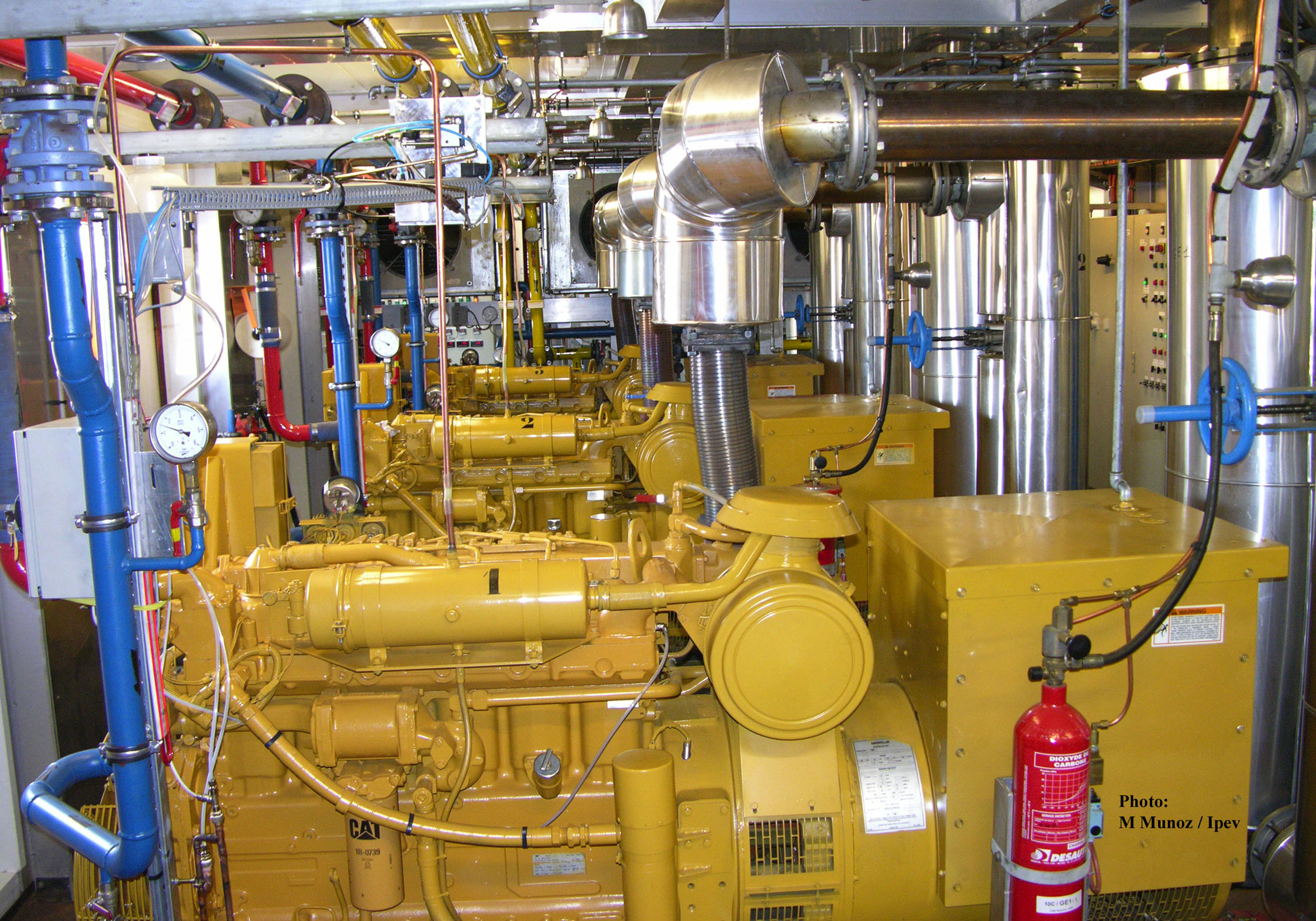
Taking into account electricity production, provided by thermal generator sets, the engine cooling system was designed in conjunction with a system for recovering the heat produced during operation. With an average theoretical electricity output, estimated at the design stage, of 90 kW, equivalent power outputs are, through efficiency losses, rejected both into the cooling circuit and into the combustion gases. The average total recoverable thermal rejection has been estimated at 115 kW – 90% of the 90 kW lost via the cooling circuit and 40% of the 90 kW lost via the exhaust.
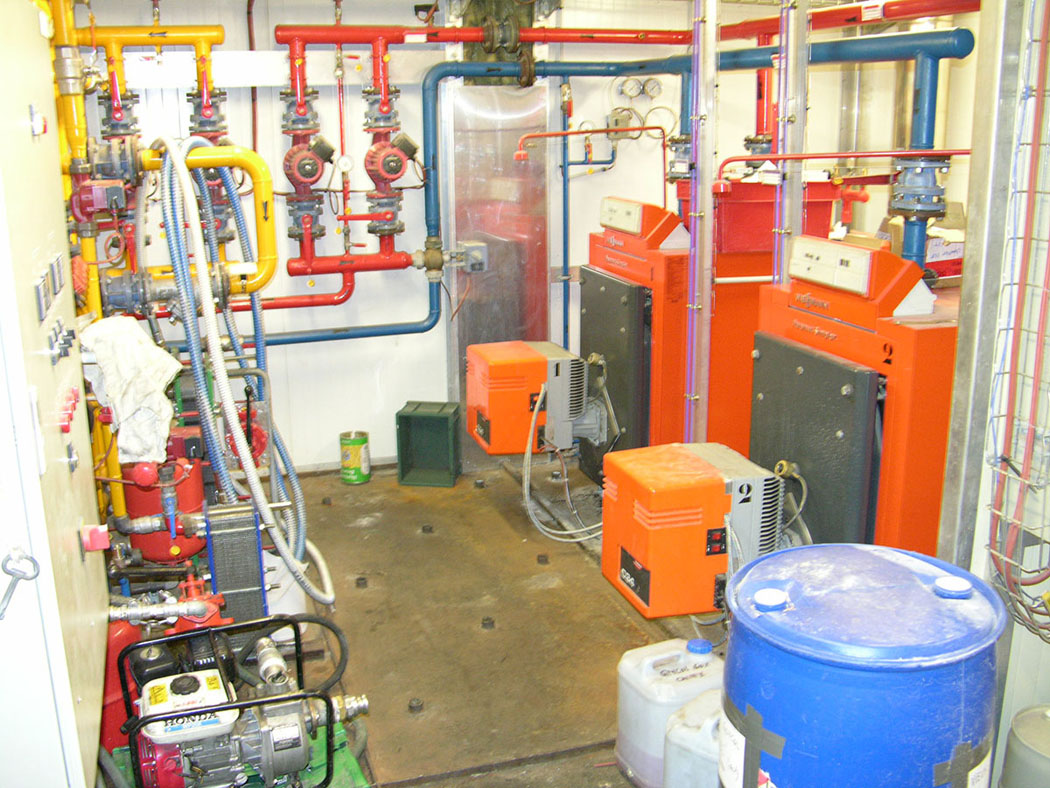
As this heat is used mainly to heat the buildings, cooling units have also been installed in case thermal dispersion within the buildings proves insufficient, along with a boiler room in case the heat recovered from the engines falls short of requirements.
Thermal insulation calculations for the buildings were based on this level of available heat. The substantial wall thickness is 160 mm – 152 mm of insulation and 2 x 4 mm of glass-epoxy composite skin.
View of generators
Exchange circuit
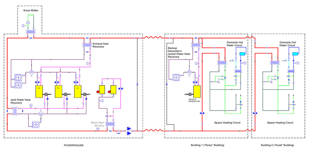
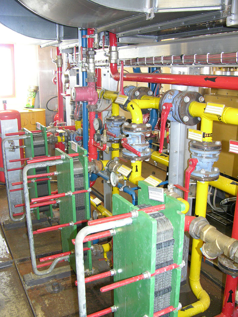
The main exchange circuit, or primary circuit (shown in dark red on the diagram), connects the heat-generating units – the engines of the main power station’s generator sets, the boiler room, the standby power station’s engine – to the utilisation circuits (shown in blue). The secondary cooling and engine exhaust circuits, along with the boiler room, are connected to the primary circuit via plate heat exchangers. The same applies to the user circuits – the snow melter, the heating circuits and the domestic hot water circuits. Regulation is provided by non-electric proportional 3-way valves.
Bypasses allow all or part of a circuit to be isolated in the event of a fault. Redundant backup systems can replace a failed heating unit – the power station’s fuel-oil boilers are backed up by electric boilers. Each building’s heating circuits are likewise backed up by electric boilers. The whole system has been running for over 20 years; the fuel boilers average around 60 hours of operation per year. Fuel consumption for electricity production and heating remains stable at approximately 275 m³ per year.
Cogeneration heating cooling exchangers
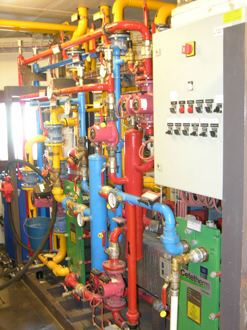
Cogeneration heating cooling exchangers